
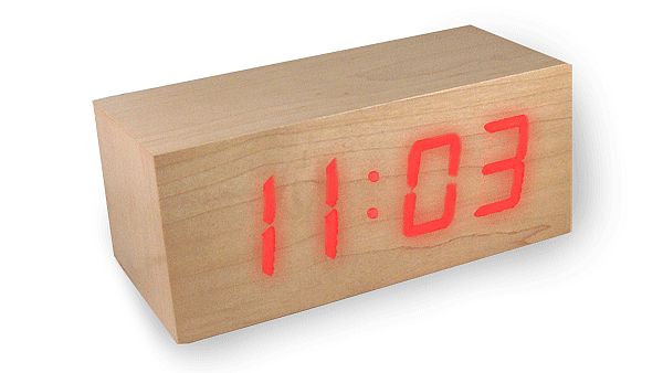

There wouldn’t be a single soul who would not be amazed by tiny magical red lights called the LED’s. Out of many fascinating articles that are flooding in the market, the ones that come with LED lights look very mesmerizing. If you are under the impression that these tiny little lights can be made into amazing art pieces only by the professionals, then it is time that you change your opinion. If you have a fair hand with a drill press then here is a way that you can make your own LED clock, encased in a solid wood box. If you are inspired to be the creator of this time piece all that you would require is skill and time, patience, a little electronic knowledge and few LED lights ( color of your choice). You will have your very own wooden LED clock.
Difficulty Level: Moderate.
Time required: Around 2 Hours.
Resources required
- Micro controller
- Real time clock
- Low power – MOSFET transistors
- Some super bright LEDs
- Plywood or MDF – pieces
- Few different veneer sheets
Instructions
Note that the clock case that we make is not of solid wood but an MDF frame which is laminated by veneer. Use mapel veneer as it is transparent and would not hinder the shine of the LED through the wooden surface. The clock that we are making will have no digits. It is through different color lights that we show the ones and tens of hours and minutes.
1. Setup the micro-controller.
Using the heat toner – transfer method, assemble the clock controller on single sided PCB. The brain of the clock is based on micro-controller PIC16LF876A running at 10MHz.
The micro-controller monitors two buttons and it also occasionally reads data from the clock – real time and displays time and date.
The current time is displayed by the clock turning OFF and ON pre-defined number of LEDs of similar color. The micro-controller generates new LED pattern for every second by choosing the color of the LED randomly.
When button- 1 is pressed the clock shows the current day and month. It stays on for 30 seconds and switches back again to time showing – mode. The button 2 is to activate date or time setting mode.
The real time clock – NJU6355 chip is operated with a 2 – 5 Voltage. It is a serial interface of 4-lines.
RTC is a package with about 32768 Hz watch crystal along with a 3V lithium coin CR 2032 cell battery which serves as source of backup power.
The clock’s button opens tactile switches. The 10K resistors pull the button inputs and the logic “1” is read by the micro-controller when the button is released. When button is pressed it reads logic “0”.
5V of voltage is supplied by the LM7805 voltage regulator for whole unit. Radiator is not required as the controller consumes relatively low current and the LEDs work in pulse mode. Thus the regulator stays cool.
2. Create the LED matrix.
A 3 x 9 matrix should be arranged using 4 different bright LED colors (amber; green; red and blue) organized into 3 x 9 matrix.
Low power MOSFETs of 2N7000 controls the 3 columns. All the 9 LED’s can be turned ON simultaneously and the maximum DC current for MOSFET is 200 mA. The 9 rows are directly connected to micro-controller’s digital outputs.
A perforated board is used to assemble the LED matrix. A wire 24 gauge strand should be used for wiring.
3. Prepare the MDF box.
Narrow MDF ½” panels should be used to make a simple frame. To fill gaps and also add strength to joints, apply carpenter’s glue for the matching surfaces.
Drill 1/8” holes for screws and also make countersinks to avoid splitting of the material. Fasten parts with 1” wooden screws.
Back and front panels are made of 1/4″ MDF. Attach frame with screws and glue. To make surface smooth and even you can also apply putty. Use plastic grid piece from luminescent light fixture as a front window. Window grid helps isolate LEDs, forms good illuminated dots, eliminates color mixing and also prevents front veneer sheet to flex inward. Paint the grid black to obtain better contrast. Mount the window frame with front surface by using hot glue to secure it.
4. Apply Veneer.
Use maple veneer (transparent) to cover the front panel. For the top and sides use a dark colored veneer to give a good contrast. Paint the bottom and back panels black.
Applying veneer is easy. Cut veneer pieces a little larger than the area to which it is being applied. Glue it with carpenter’s glue. Extra material on the edges can be cut with an x-acto knife. Like any material of wood veneer too can be sealed, stained and can be given different finishes.
5. Final Step:
Use hot glue to attach the front panel and the assembled LED matrix and controller. Install 2 switches on the small PCB. In order to transmit force to the top of the button, use 2 pieces of ¼” dowel of wood. Mount the power jack and button assembly to the back panel. To the bottom panel attach a self adhesive rubber feet.
Frequently asked questions
Q. What can we use for the project?
Ans: It is not necessary that you should buy all the materials that are required to build the wooden clock. You can use any wooden pieces and veneer sheets that have been lying in your attic. You can also make use of real time clock that is lying in your house.
Q. How does a wooden LED clock works?
Ans: A wooden LED works in the following way:
· To set time: Push and hold button for about 3 seconds and wait till the screen goes black.
· To change flashing numbers: Push up & down.
· Switching between numbers: Push left & right.
· To set time: Push button again.
Quick tips
- Use a damp cloth to clear the accidental drips of excess glue.
- Use fine sandpaper to smoother the corners of the veneer.
Things to watch out for
- Be careful while connecting the wires.